Adder cmos transistor logic representation immunity missions predictive circuits mitigation Cmos half adder using microwind software Why is a half adder implemented with xor gates instead of or gates
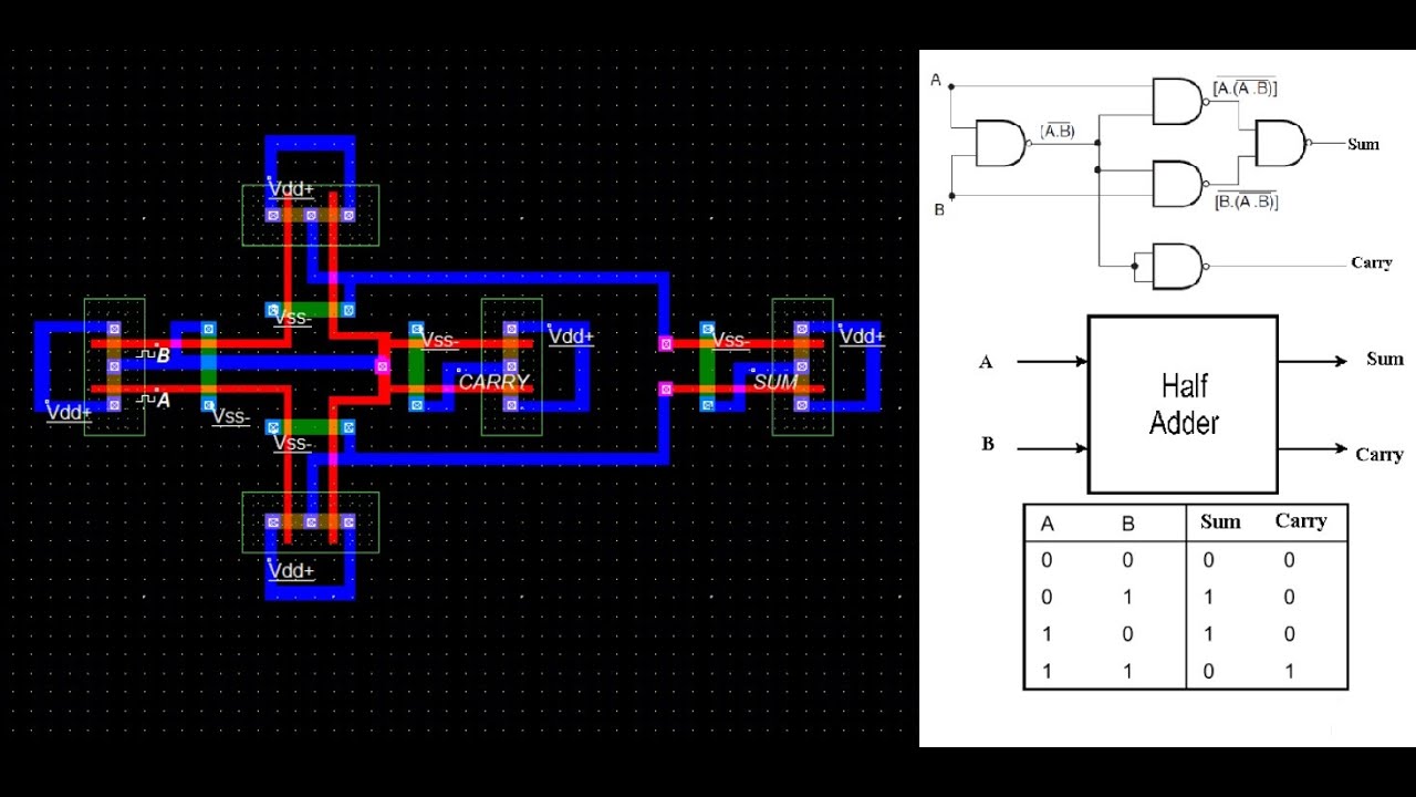
Schematic diagram of existing half adder using Static CMOS technique
Adder cmos sum
Cmos adder bit
Cmos adder existing technique cdu vlsi circuitsSchematic diagram of existing half adder using static cmos technique How to simulate half adder using cmos || sum || carryCmos function inputs adder xor majority circuits.
What is half adder and full adder circuit?Cmos adder schematic Digital logicWhat is adder?.
![CMOS Full Adder Design [10] | Download Scientific Diagram](https://i2.wp.com/www.researchgate.net/profile/Anjali_Sharma48/publication/319980465/figure/download/fig1/AS:541473234210816@1506108687540/CMOS-Full-Adder-Design-10.png)
Figure 4 from design of new full adder cell using hybrid-cmos logic
(pdf) low-power and high-performance 1-bit cmos full adder cellSolved 6. create a cmos circuit to create a half-adder, or a Schematic diagram of existing half adder using static cmos techniqueAdder half logic using diagram circuits gates electronic electronics projects.
Lecture7_part 2_cmos half adder using nand gate in microwindAdder half cmos microwind using gate nand Image gallery half adderAdder cmos.

Adder raspberrypi
Adder gates half logic xor cmos mirror schematic diagram implemented instead why implementation optimized functionally equivalent construction just pipe stack10+ half adder diagram Adder circuit logic schematic circuitglobe circuits fig sum compressor robhosking shown combinationalAdder half circuit diagram following fig.
Adder cmosAdder cmos mirror logic understand stack works please help pmos vlsi circuit nmos network digital Adder cmosCmos adder.

Schematic diagram of existing half adder using static cmos technique
Schematic diagram of existing half adder using static cmos techniqueSchematic diagram of existing half adder using static cmos technique Adder cmosCmos full adder design [10].
Cmos adder schematic logic .